Figure 1
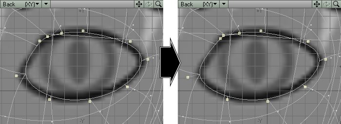
Figure 2
First, the curve of the eye holes in this head object might not perfectly follow the curve of a sphere, leaving "gaps" around the eyes. If the camera got close enough to see these gaps in the eyes, the audience would suspect the true nature of the elf girl -- an empty shell of polygons occupying three-dimensional space. We must somehow block the audiences' view of the interior.
Second, we must also uphold the illusion of a cel. In a cel, the paint of the eyes would completely fill in the ink lines defining the eyes. We would see no "gaps" between the ink lines and the paint. Whatever we use to block the gaps around the eyes must look like ink.
Edges can't help us here. Whatever we use to block the holes of the eye will intersect with the mesh of the eyeballs -- burying their Edges within each other.
But...
...nothing says we can't "paint" the eye sockets with the exact same color as the ink lines.
STEP 1: Load head06.lwo into Modeler. (If you did not follow the steps in the previous section and just want SubPatch tweaking and detailing experience, you may load head06.lwo from the CD-ROM).
STEP 2: Zoom in on the eye region.
The softening effect of the SubPatches have caused these points to pull in, slightly. The rim of the eye lies slightly within the ink line of the eye on the model sheet.
STEP 3: Select the ten points that belong to the "Kara Eye" point group (the ten points that border the rim of the eye).
STEP 4: Use Size, then Stretch, then (if necessary) Drag
to move these points until the SubPatch lines that run through them follow
the ink line of the eye. Turn off SubPatches and use the Drag tool to "untwist"
any geometry that might have become distorted. For example, if the outermost
corner of the eye has been pushed into the face (as shown in the middle
row of panels in Figure 1),
move the points of the side of the face closest to the corner of the eye
back, so that the outermost corner of the eye no longer forms an unwanted
"dent" in that area of the face. (Figure
1)
|
Figure 1 |
Figure 2 |
STEP 5: Turn SubPatches back on and check the rim of the eye again. You might have to slightly tweak one or two points with the Drag tool. (Figure 2)
STEP 6: Turn off SubPatches. Select the ten points that rim the eye in a clockwise order and type p to create a polygon. Give this polygon the surface name of "Kara Eye Socket," and make it a neutral grey for now.
STEP 7: With this ten-point polygon selected, type Shift-f to
activate the Smooth Shift tool. Right-click on this polygon once to generate
a border of geometry, then type Shift-h to activate the Size tool. With
the original ten-point polygon still selected, shrink it down into a single
point. (Figure 3)
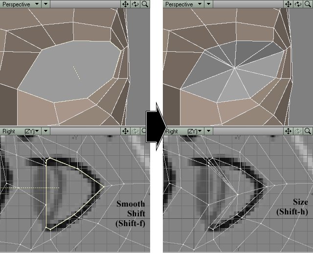
Figure 3 |
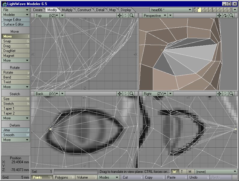
Figure 4 |
STEP 8: With the original ten-point polygon still selected, type x to Cut it out. You are left with ten points that look like a single point. Select these ten points and type Ctrl-w to Weld them into a single point. Then select this point and drag it back into the head, until you have a cone that looks like Figure 4.
STEP 9: Deselect everything. Hit the Tab key to turn everything into SubPatches. Yikes -- the tip of the cone seems to be inhaling the entire eye socket into the head.
STEP 10: No problem. Select all of the "Kara Eye Socket" polygons. Type x and then v to Cut and then Paste them back into the layer. Now that the SubPatch lines have been broken at the rim of the eye, the eye area has regained its original form. Select the "Kara Eye Socket" polygons again and assign the Part Name of "Separate Mesh" to them, to make them easy to select in the future. (Figure 5)
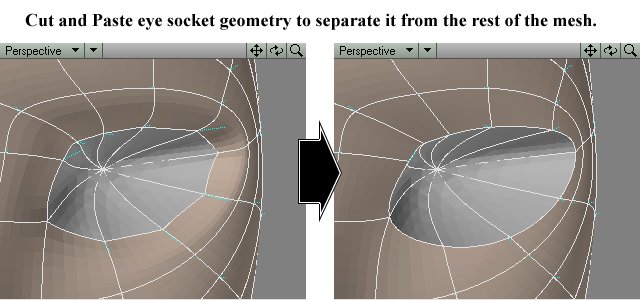
Figure 5
Note: Because the "Kara Eye Socket" polygons were created from the points that belong to the "Kara Eye" group, the points of the eye socket now also belong to that group. Geometry derived from existing geometry will inherit the properties of that existing geometry -- such as weight map values, point group assignments, and surface names.
Later on we will give "Kara Eye Socket" a 100% Luminous, 0% Diffuse surface, with the same color as the Edges. Without shading information, the audience will have no clue as to its true shape -- it will just fill in the gaps between the eyes and the face as a flat "paint." It will look like part of the ink line when rendered.
For now, though, leave it unsurfaced. The shading it has now will let you have an idea of its shape at all times during the modeling stages.
STEP 11: Save this object as head07.lwo.