Figure 1
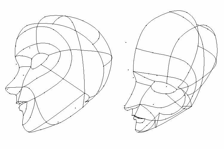
Figure 2
This section assumes that you know information from either the LightWave manual or the previous tutorial sections in this chapter.
If you have not followed any of the previous tutorial sections and do
not know these techniques, please review at least the spline exercises
from the CD-ROM. Following the torso spline cage tutorial before constructing
the head is also strongly recommended.
|
Figure 1 |
Figure 2 |
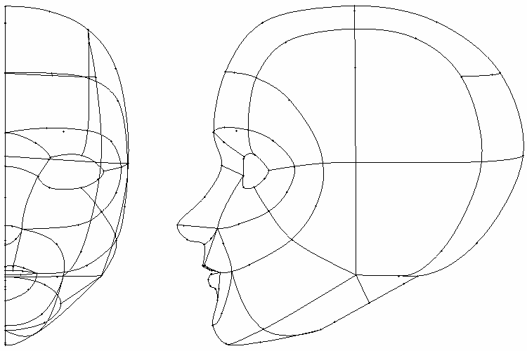
Figure 1 and Figure 2 show the spline cage that we will create for this elf-girl's head. This cage is specifically intended for a celshaded mesh -- it uses the fewest number of patches in order to get the smoothest possible surface.
The simplicity of this cage comes at a price -- note the six splines
joined at the corner of the nose. This means six SubPatches will be tugging
on that corner of the nose when this cage is patched -- a dangerous situation
for a photorealistic model. A celshader can ignore this problem, however,
unless it threatens to generate an unwanted ink line.
Before you do anything else, take a look at the upper-right hand corner of Modeler, at the area directly above the Perspective View window. Note that the name of your object ("torso27.lwo") appears to the left of the layer-selection triangles in a drop-down list box.
STEP 2: Type Shift-n to start a new object (File > New Object).
STEP 3: Your model disappeared! ...or did it? Check that drop-down list box above the Perspective View window. It now says "Unnamed." Left-click on it, and hold down the left mouse button. Two names are listed on it -- "Unnamed" and..."torso27.lwo." Select "torso27.lwo" from the list to return to that object file.
Note: Just as each model can now have infinite layers, Modeler can let you work on several models at once. Use the drop-down list box above the Perspective View window to switch between the models you want to work on in Modeler.
STEP 4: Return to "torso27.lwo." Go to the layer that
contains the body. Select the eight points that ring the top of the neck,
the points to which the head will later attach. Type c to Copy these points.
(Figure 3)
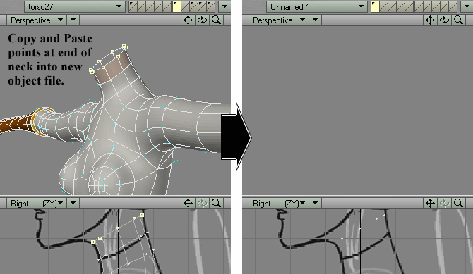
Figure 3 |
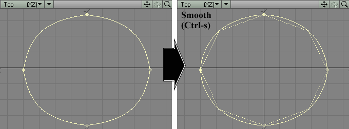
Figure 4 |
STEP 5: Return to "Unnamed" and paste these eight points into the empty layer of your choice.
STEP 6: Starting with the topmost point in the Top View, select the two points to its right and create a spline. Create three more splines, until it looks like Figure 4. Type Ctrl-s to Smooth the curves of this spline circle.
STEP 7: Deselect everything. In the Right View, create 11 points
as shown in Figure 5
and type Ctrl-p to create a spline.
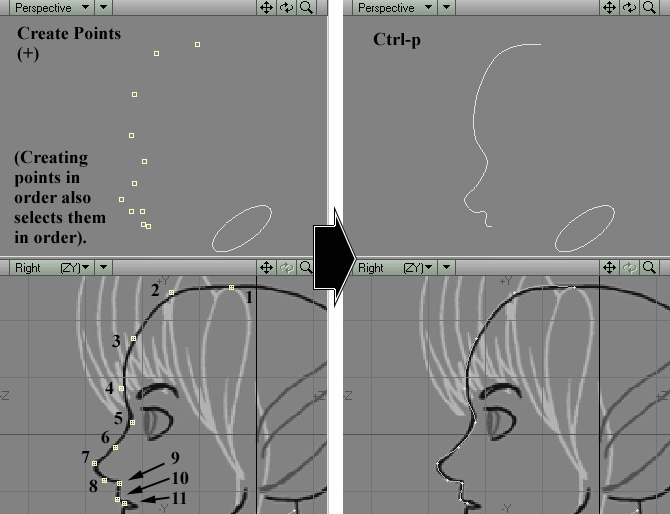
Figure 5 |
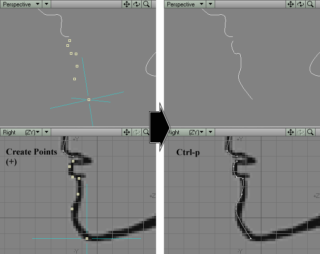
Figure 6 |
STEP 8: Deselect everything. In the Right View, create seven points as shown in Figure 6 and type Ctrl-p to make a spline.
STEP 9: Use the Drag tool to make these two "profile" splines
trace the ink lines of the model sheet. (Figure
7)
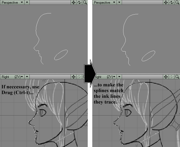
Figure 7 |
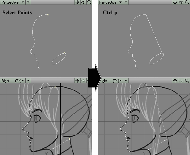
Figure 8 |
STEP 10: Select the two points shown in Figure 8 and type Ctrl-p to create a spline.
STEP 11: Select the two points shown in Figure
9 and type Ctrl-p to create a spline.
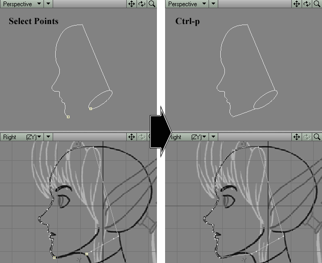
Figure 9 |
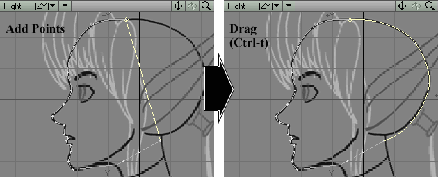
Figure 10 |
STEP 12: Add four points to the spline that connects the top of the head to the back of the neck circle. In the Right View, Drag these four points to make the spline trace the ink line defining the back of the head. It should look like Figure 10.
STEP 13: Select the two points shown in Figure
11 and type Ctrl-p to create a spline.
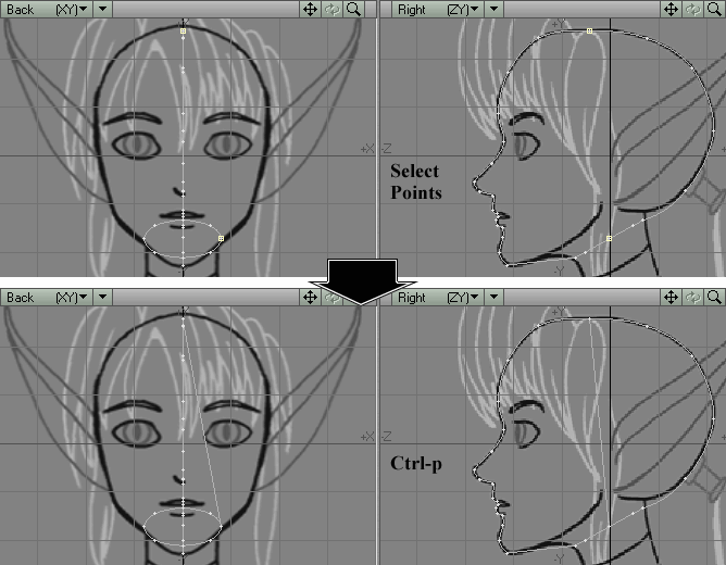
Figure 11 |
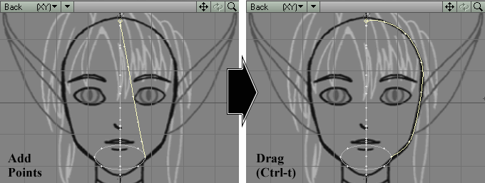
Figure 12 |
STEP 14: Add five points to this new spline. In the Back View, Drag these four points to make the spline trace the ink line defining the side of the head. It should look like Figure 12.
STEP 15: Now for the jaw line. Select the two points shown in
Figure
13 and type Ctrl-p to make a spline.
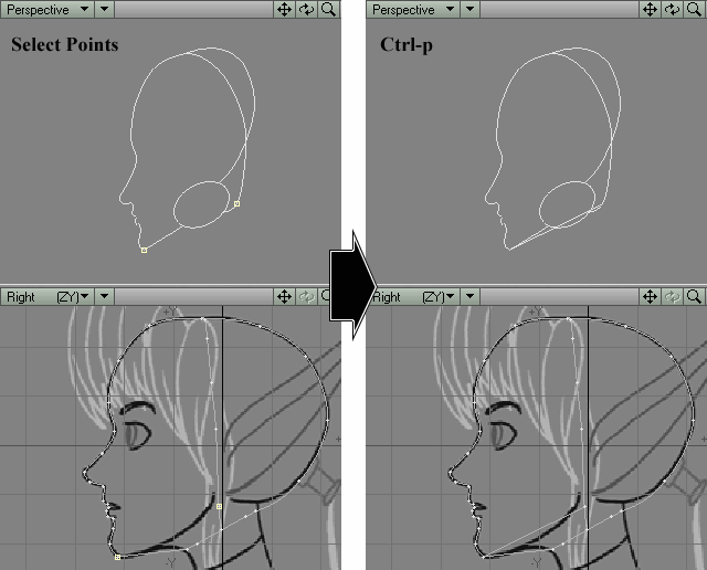
Figure 13 |
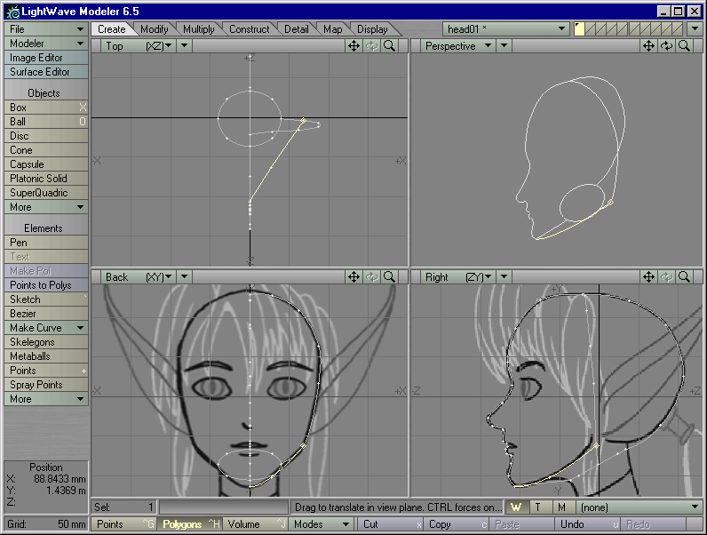
Figure 14 |
STEP 16: Add a point to this spline and Drag it until the spline traces the line of the jaw. (Figure 14)
STEP 17: Zoom in on the mouth area. Create a point that lies
in the corner of the mouth in each View, as shown in Figure
15.
Figure 15 |
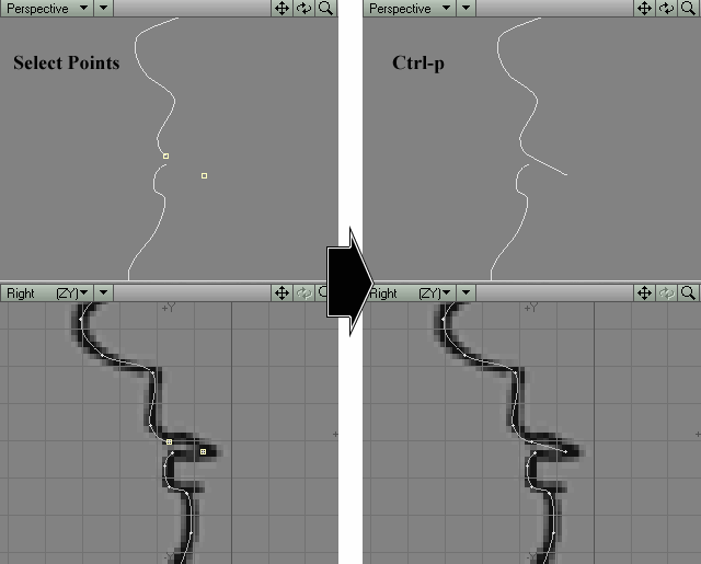
Figure 16 |
STEP 18: Select the two points shown in Figure 16 and type Ctrl-p to create a spline. This spline will later define the upper line of the mouth.
STEP 19: Select the two points shown in Figure
17 and type Ctrl-p to make a spline. This spline will later
define the lower line of the mouth.
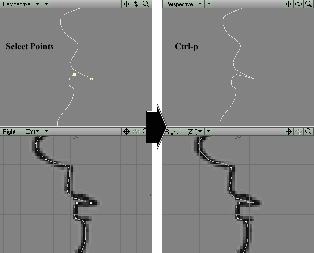
Figure 17 |

Figure 18 |
STEP 20: Add a point to the spline defining the upper line of the mouth, and Drag it until it bows outwards in the Top View, and it matches the ink line of the mouth in the model sheet in the Back and Right Views. (Figure 18)
STEP 21: Add a point to the spline defining the bottom line of
the mouth, and Drag the new point until the spline bows outwards in the
Top View and matches the ink line of the mouth in the model sheet. (Figure
19)
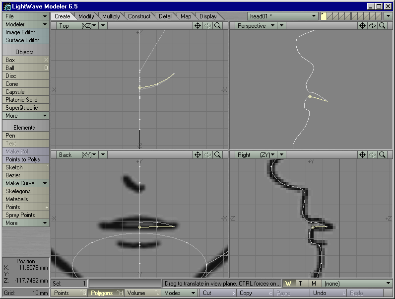
Figure 19 |
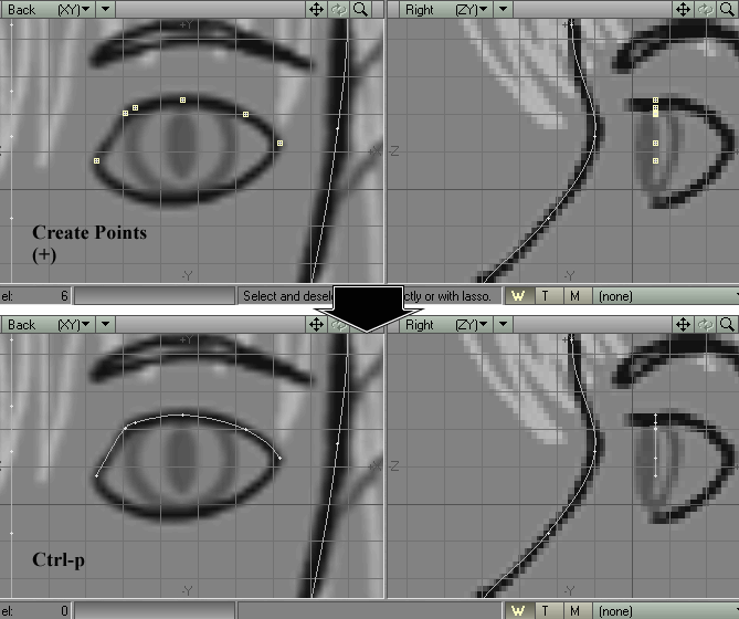
Figure 20 |
STEP 22: Zoom in on the ink line of the eye. Create six points along the ink line defining the top of the eye (line up the initial point in both the Back and Right Views, but add all subsequent points in the Back View. It's all right to have a "flat" set of points right now). Type Ctrl-p to create a spline. Use the Drag tool if you must to get the spline to trace the ink line of the model sheet -- placing two points close together at the sharp upper-lefthand corner of the eye. Placing those two points close together will sharpen the curve of the spline in that area. (Figure 20)
STEP 23: Select the lowest two points of the "eye spline," and
type Ctrl-p to create a new spline. (Figure
21)
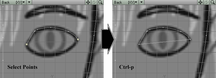
Figure 21 |
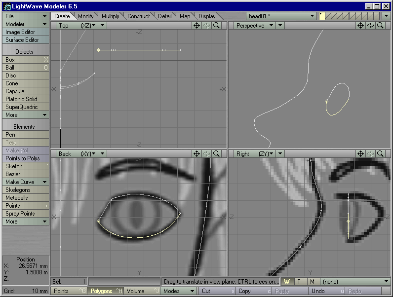
Figure 22 |
STEP 24: Add three points to this new spline. Drag the three points in the Back View until the lower "eye spline" traces the lower ink line of the eye in the Back View. (Figure 22)
STEP 25: Now let's make the eye-splines match their ink line counterparts in the Right View. Deselect everything. Select both eye splines. Type [ to activate the Shear Tool (Modify > Move > More > Shear Tool). In the Back View, right-click slightly to the left of the center of the eye, and drag your cursor to the right to define the falloff of the Shear effect. Use your right mouse button to tweak the ends of the blue falloff triangle if you wish. Then tap the "up" arrow button on your keyboard until the triangle looks skinny with a wide base (meaning that the Shear effect will happen mostly towards the end of the triangle). Left-click in the Top View and (holding down the Ctrl key to restrict movement to one axis) drag your cursor up until the outer corner of the eye-splines touches the ink lines of the eye in the Right View. (Figure 23)
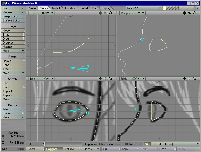
Figure 23
You should now have a spline cage that traces the main ink lines of the face in the model sheet. Save it out now as head01.lwo.