
Figure 1
In Modeler, a spline describes a line or curve in 3D space. Three or four splines lashed together with shared points describe a surface. Spline "patching" converts this description of a surface into a true polygonal surface. (Splines themselves will not show up in a render in Layout).
Any tool that generates three- or four-point polygons in Modeler can double as a SubPatch tool. While you may sometimes start with a primitive volume, such as a box, you will often run into shapes that defy primitives. The plastic container for an American gallon of milk, for example, does not look like a box, a cone, a disc, a ball, or any other primitive shape.
Enter spline modeling.
Spline patching generates entire sheets of four-point polygons, distorted to fit any shape you can describe with lines. With spline patching, you describe your own "custom" volumes - a gallon of milk, a human torso, even a human head. A spline cage also needs fewer points to describe an object than an equivalent SubPatch cage, which makes the spline cage easier to construct and edit. This freedom of form and editing speed makes splines one of the most powerful SubPatch modeling tools available.
Yet splines remain one of the most overlooked and misunderstood tools in Modeler.
The following exercises should take most of the mystery out of using splines.
Figure 1
STEP 1: In Modeler, type + (that's holding down Shift and tapping the = sign key, folks) to activate the Points Tool (Create > Elements > Points). In the Back view window, move the mouse pointer to about -1m on the X axis and 1m on the Y axis and left-click the mouse. A point will appear where you have just clicked. It will be highlighted and a blue crosshair will be on top of it for good measure. (Figure 1)
|
Note: This point's resting place will not be fixed until: a) you deactivate the Points Tool. b) you activate another tool. c) you edit the point with a keyboard shortcut. d) you make a polygon or spline with the point. e) you move the cursor to another place and right-click to drop another point. |
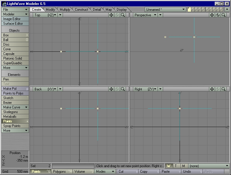
Figure 2
STEP 2: Move the mouse pointer to about 1m on the X axis and 1m on the Y axis and right-click the mouse. A new point will appear. (Figure 2)
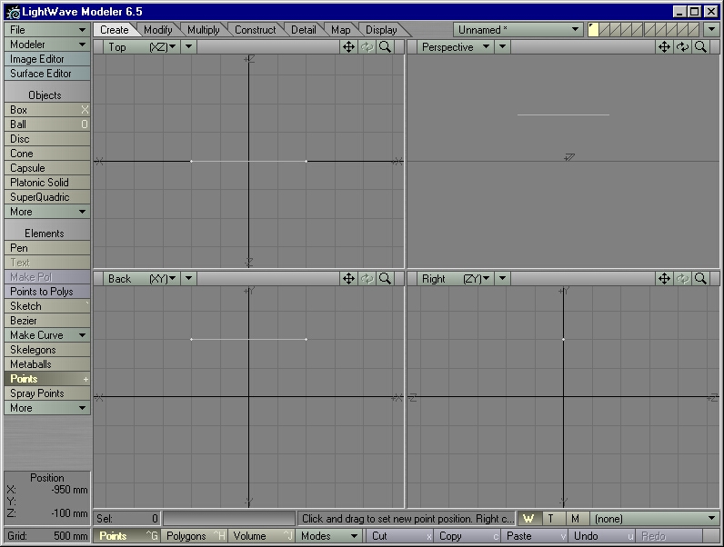
Figure 3
STEP 3: These points are already selected, so hit Ctrl-p to create a spline (Create > Elements > Make Curve > Make Open Curve). (Figure 3)
| Note: Though the blue crosshairs have disappeared from the point, the Points Tool itself is still active. |
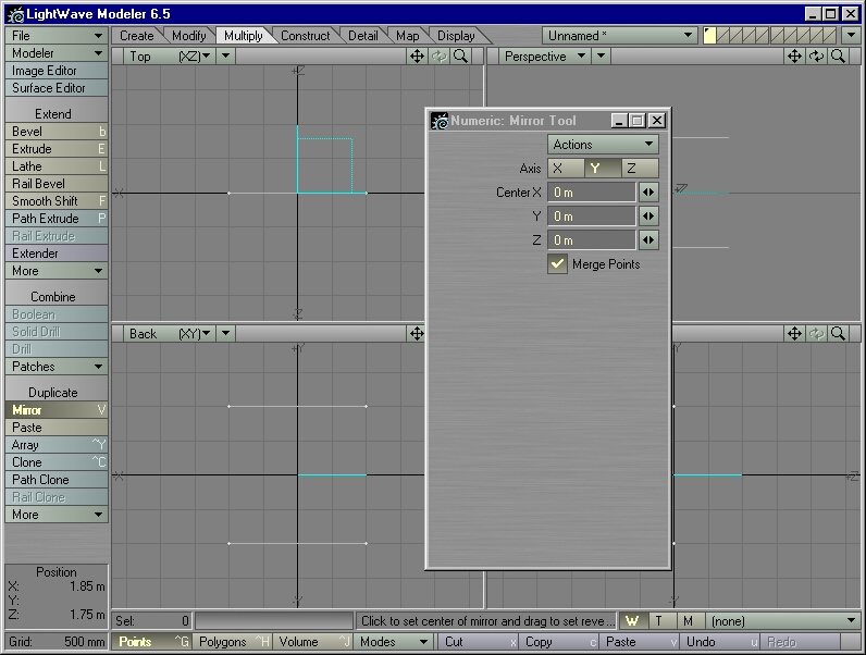
Figure 4
STEP 4: Type Shift-v to activate the Mirror Tool (Multiply > Duplicate > Mirror). Press n on the keyboard to bring up the Numeric Panel (Figure 4). In the "Actions" drop-down list, select Activate. For the Axis, select Y. It doesn't matter whether or not Merge Points is selected, since no points will overlap each other when the spline is mirrored. Close the Numeric Panel.
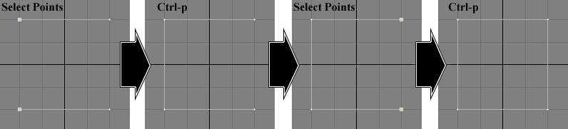
Figure 5
STEP 5: Type Ctrl-g to enter Point Selection mode. Note how the arrangement of points in the Back View looks like a square. In the Back View, hold down the left mouse button and move the mouse pointer over the upper left-hand "corner" point to select that point. Then (without lifting your finger from the left mouse button) drag the mouse pointer down until it touches and selects the lower left-hand "corner" point. (If you let go of the mouse button, hold down the Shift key. Now you can add more points to your selection, by left-clicking on them). It should look like the first panel of Figure 5.
STEP 6: With these two points selected, type Ctrl-p to create another spline (Figure 5, second panel).
STEP 7: Select the two rightmost points (Figure 5, third panel) and type Ctrl-p to create a fourth spline (Figure 5, fourth panel).
STEP 8: Save this object as splinebox.lws so that you can experiment with it in the future.
You have just created a spline description of a surface. This description has four sides (four splines) joined at the corners (sharing points at the corners).
| Note: A spline description may have as few as three sides (splines), but never more than four. |
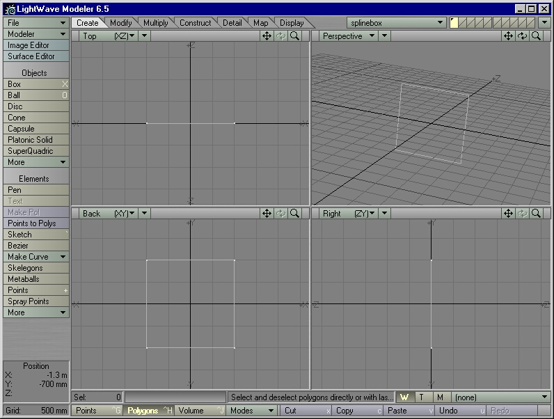
Figure 6
STEP 9: Move the mouse pointer to the Perspective window. Holding down the Alt key and the left mouse button, drag the mouse pointer around to rotate the view of the Perspective window. (If you prefer, you may ditch the Alt key and just use that little "rotate" icon in the upper right-hand corner of the Perspective window. Use whatever feels most comfortable to you). In Figure 9, notice how it merely describes the boundaries of a surface - this is not something that you can render in Layout. (Figure 6)
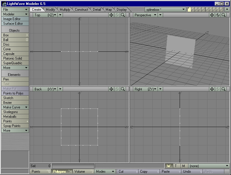
Figure 7
STEP 10: We have two ways of turning this boundary into something that you can render. The first way is to merely Freeze this boundary. Type Ctrl-d (Construct > Convert > Freeze) and see the results in the Perspective window. We should have something that looks like Figure 7 - a single polygon (albeit one with a lot of points). Notice that we have also lost the original spline boundary.
STEP 11: Type u to Undo the Freeze command. We should now have the original spline boundary again.
The second way of generating geometry from a spline description will leave the original spline boundary intact. Spline patching fills in the spline boundary with a sheet of four-sided polygons.
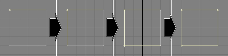
Figure 8
STEP 12: Type Ctrl-h to switch to Polygon Selection mode. Click outside the grid areas to deselect all polygons. In the Back view window, move the mouse pointer to the topmost spline. Holding down the left mouse button, select the splines in the order of Figure 8 - first the topmost spline, then the leftmost spline, then the lowest spline, then the rightmost spline, in that order (counterclockwise).
When all four splines are selected, type Ctrl-f to bring up the Patch Tool (Multiply > Combine > Patches > Make Spline Patch). Type in 6 for Perpendicular, and 6 for Parallel, and then click on OK (Figure 9).
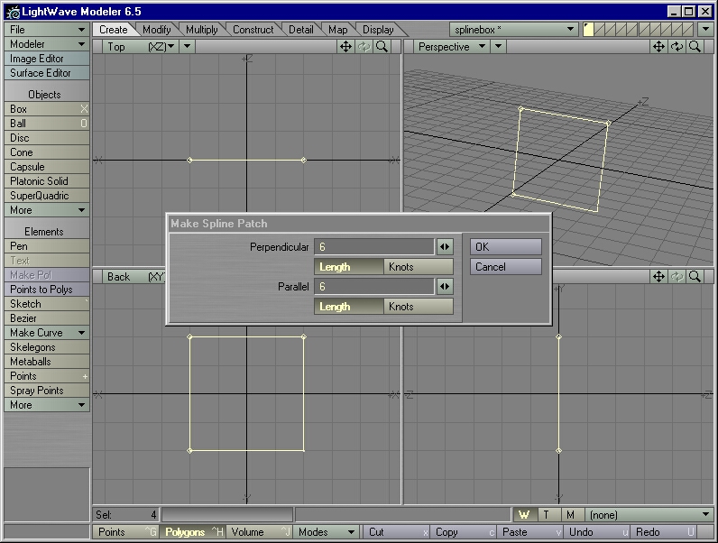
Figure 9
We should now have something that looks like Figure 10 - a 6 by 6 mesh (or "patch") of polygons filling in the spline boundary.
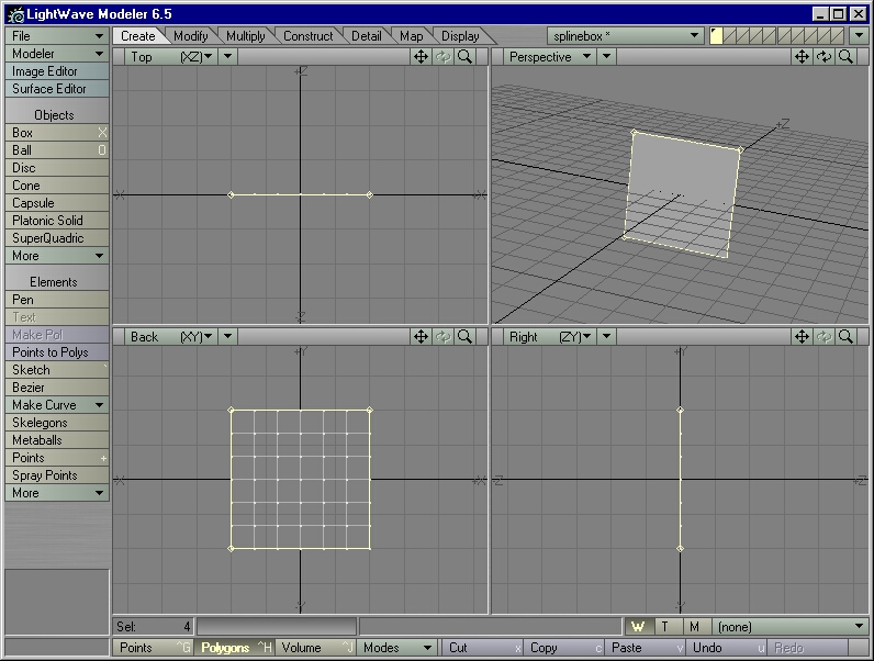
Figure 10
STEP 13: Type u to Undo the Patch operation. The patch of polygons has disappeared, but the splines remain selected. The splines also remember the order in which you selected them. Type Ctrl-f again. This time type in 6 for Perpendicular and 3 for Parallel. Click on OK and look at the results (Figure 11).
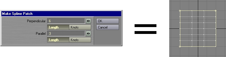
Figure 11
We should have a 6 by 3 patch, with strips of three four-point polygons running parallel to the first spline selected (the topmost spline). Also, strips of six four-point polygons run perpendicular to the first spline selected.
STEP 14: Type u to Undo the Patch operation. Then type Ctrl-f again. This time type in 3 for Perpendicular and 6 for Parallel. Hit Enter and look at the results.
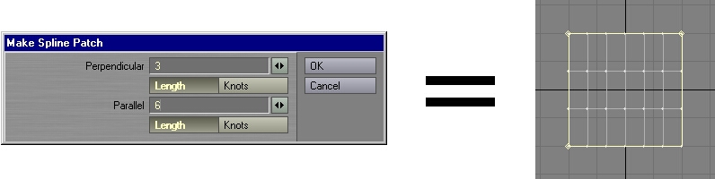
Figure 12
We should now have a similar patch to the previous one, save that the strips now run in different directions (Figure 12).
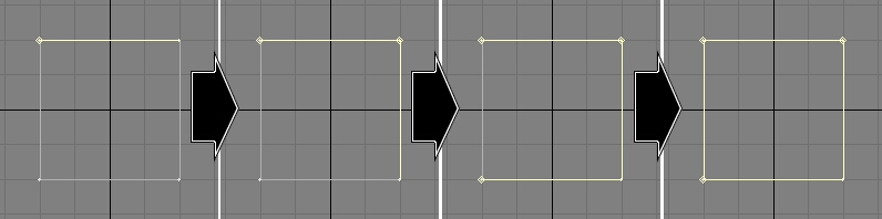
Figure 13
STEP 15: Type u to Undo the Patch operation. Now deselect everything by left-clicking outside of the grid area. Select the splines in a clockwise fashion this time, starting with the top spline, then the right spline, then the bottom spline, and finally the left spline (Figure 13).

Figure 14
STEP 16: Type Ctrl-f and Patch these selected splines with whatever settings you like. Note that the resulting polygons now face away from you - rotate the view in the Perspective window to see for yourself (Figure 14).
|
Tip: Technically, it doesn't matter what order in which we select the splines - we will always get a patch, as long as we select the splines that define a three- or four-sided boundary. The direction in which the patch faces, however, depends on the order in which we select the splines. Knowing this little detail about spline patching will increase your modeling speed. Select the splines in a counterclockwise fashion to make the normals of the patch face towards you. Select the splines in a clockwise fashion to make the normals face away from you.
(People accustomed to creating geometry point-by-point should note that this is the opposite of creating a single polygon from selected points. For those unfamiliar with creating a polygon point-by-point, selecting points in a clockwise fashion and tapping p creates a single polygon whose normal faces towards you. Selecting the points in a counterclockwise fashion and tapping p creates a single polygon whose normal faces away from you). |
STEP 17: Undo the Patch operation and deselect the splines. Let's see what happens when one of the splines in the spline boundary has more than two points. To turn a two-point spline into a three-point spline, we must add a point to the spline. The quickest way to do this is the Add Points tool.
STEP 18: Type Ctrl-g to enter Points Selection Mode, and make sure that no points are selected.
Note: If any points are selected in Points Selection Mode, Add Points will add those points to the spline, instead of creating and adding a brand-new point.
STEP 19: Type Ctrl-h to enter Polygon Selection Mode. Select the topmost spline.
STEP 20: Activate the Add Points tool. (If you have not assigned a hot key for this tool yet, you'll find it in Construct > Subdivide > More > Add Points. You may want to assign a keyboard shortcut for it, though).
STEP 21: With the Add Points tool activated, move the mouse pointer to the center of the topmost spline and left-click on the spline itself. If no points were selected in Points Selection Mode, the Add Points tool will create and add a new point where you clicked on the spline.
|
Warning: At the time of this writing, Add Points behaves unpredictably in LightWave 6.5. On a spline it will often add the point not where you clicked on the spline, but instead on an imaginary line that connects the two end points of the spline, snapping the spline to the newly added point. This bug should be fixed by the time of this book's publication, but if you have an older version of 6.5, you may run into this bug. In Step 21, if Add Points does not place the new point in the center, type Ctrl-t to bring up the Drag tool and (while holding down the Ctrl key to restrict its movement to one axis) Drag the newly added point to the center of the spline.
|
The topmost spline should now be made up of three points, instead of two, with a point right in the center.
If any points had been selected in Points Selection Mode, you might have seen the center of the spline suddenly snap to those points, and the spline would have then run through those points.
If the point or points selected in Points Selection Mode had already belonged to the spline (in this case, the points that make up the upper corners of the spline boundary), they also would have been "added" to the spline. However, because they had been part of the spline to begin with, it might not look like anything had changed. In frustration, you might keep clicking on the spline - unknowingly "adding" more and more points to the spline. Selecting the points to see how many points define the spline would have revealed nothing - they're still the same two points. The spline curve, however, would have been "looping" through one or more of those same points again and again and again. If you had tapped i in Polygon Selection Mode to bring up the Polygon Info on the selected spline, you would have found it listed as a curve of more than two points!
This can cause problems for any spline operations (such as Rail Extrude, Rail Clone, and Spline Patch) that might depend on the spacing between the "knots" (points) in the spline curve. Another "looping" case you might run into is a mysteriously sharp angle going through a single point. The fix for "looping" problems is to type m and run a Merge Points operation (with the Automatic setting) on the offending point(s). Merge Points will look at the point(s), observe that it has nothing to merge, and reply "No points eliminated." The spline, however, will clean up its act and eliminate all looping problems on the points that you "merged."
| About Add Points: Add Points will not work on an unselected spline or polygon, which is why we must have the topmost spline selected in order for Step 21 to work. It's OK to select as many splines as you want - all Add Points cares about is the spline you actually click on. |
STEP 22: Type Ctrl-h to activate Polygon Selection mode, hold down the Shift key, and select the rest of the splines in a counterclockwise manner. Type Ctrl-f and Patch the spline boundary with a setting of 6 in Perpendicular and 6 in Parallel, with Length activated in both settings. Study the result, then Undo the Patch operation and type Ctrl-f again. Leave the settings the same (6 by 6), but this time activate Knots in both settings. You should see little, if any difference.
STEP 23: Undo the Patch operation. Type Ctrl-t to activate the Drag tool (Modify > Move > Drag). Hold down the Ctrl key to restrict the Drag operation to one axis; place the cursor over the point in the center of the topmost spline, and Drag it to the left until it lies one-quarter of the way between the topmost corner points.
| Note: If you're holding down the Ctrl key and the point refuses to move, chances are you started dragging the point upwards or downwards before you tried to move it to the left. For the Drag tool, the Ctrl key restricts movement to the axis in which the point is first moved. Let go of the Ctrl key, press it again, and try to Drag the point towards the left again. |
STEP 24: Type Ctrl-f and Patch the splines with a setting of 6 by 6 with Length activated in both Perpendicular and Parallel. Look at the result. Undo the Patch operation. Type Ctrl-f again and Patch the splines again, this time with a setting of 6 by 6 with Knots activated in both Perpendicular and Parallel. Same spline boundary, same number of polygons, but different results. One of the settings gave you the the same results from earlier in this tutorial, and the other setting gave you the results seen in Figure 15.
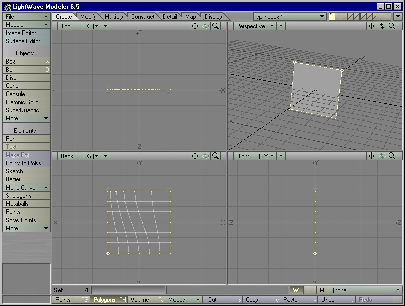
Figure 15
| 6.0 Note: LightWave 6.0 had the labels switched on the Knots and Length buttons in the Patch control panel. This bug has been fixed as of LightWave 6.5. |
|
Knots vs. Length: In LightWave, patching with "Length" activated results in evenly spaced points along the length of the spline. A patch made with "Knots" activated has its points biased according to the spacing of the points (or "knots") of the spline.
If a spline border is made up of n points, then the total number of sections on that spline border is n-1. If the patch has m number of polygons running along the edge defined by the spline border, and the patch is using Knots, then the number of polygons in each section on that edge is m divided by n-1. For example, if the spline border is made up of three points, then that spline border has two sections. If the patch has six polygons running alongside that spline border, and the patch is using Knots, then three polygons each will lie between the sections on that spline border. Undo the spline patch, type Ctrl-x, and add another point to the topmost spline. Now the topmost spline is made up of four points,which splits it into three sections. Type Ctrl-f and repatch with 6 by 6 and Knots activated. Two polygons will lie between each section on the topmost spline. Use "Length" when using splines to create a finished, high-resolution mesh for a mechanical object. With the polygons evenly spaced apart, you'll have less risk of unwanted "pinching" caused by closely spaced points in one area of the mesh. Use "Knots" when using splines to build a low-resolution SubPatch cage. SubPatches will soften and smooth almost any low-resolution mesh into an organic form, so you don't have to worry about "pinching" if the mesh is made of few enough points. Plus, on both splines and SubPatches, points spaced closely together will form a sharp angle; points spaced far apart will form a soft curve. Because splines and SubPatches agree with each other on this issue, using Knots when patching a spline cage will produce a SubPatch cage whose contours closely match that of the original spline cage. These last two tips work well in most cases, but you may choose any setting you like. Always use the setting that gives you the results you want. |
1) A spline boundary must be made up of three or four sides, with each side defined by a single spline.
2) The boundary must be joined at the corners. No more than one point may make up a corner, and the corner point must belong to both of the splines that join to form the corner.
Breaking either of these rules will cause the Patch operation to return the error message, "Curves do not cross correctly."
The order in which you select the splines controls the direction of the polygon normals in the patch:
1) Selecting the border splines in a counterclockwise fashion makes the normals of the generated patch of polygons face towards you.
2) Selecting in a clockwise fashion makes the patch normals face away from you.
If you have not saved splinebox.lwo from the previous spline tutorial, follow steps 1-8 of that tutorial to recreate it.
STEP 2: Type Ctrl-h to enter Polygon Selection mode. Select the rightmost spline. Type x to Cut it out of the geometry and into memory, then type v to paste it. Although it looks the same as before, you have just separated the spline from its neighbors.
STEP 3: Select the splines in a counterclockwise fashion and type Ctrl-f to Patch them. Choose any settings you like and click on OK. You should get the error message, "Curves do not cross correctly."
STEP 4: Enter Point Selection mode by typing Ctrl-g. Select the "point" at the uppermost right hand corner. It may look as though you have selected a single point, but the Selection Info ("Sel:") in the lower left-hand corner of Modeler says that you have selected two points (Figure 16). Hold down the Shift key and select the "point" in the lowermost right hand corner. Even though it looks like you have selected two points altogether, the Selection Info says that you have selected four!
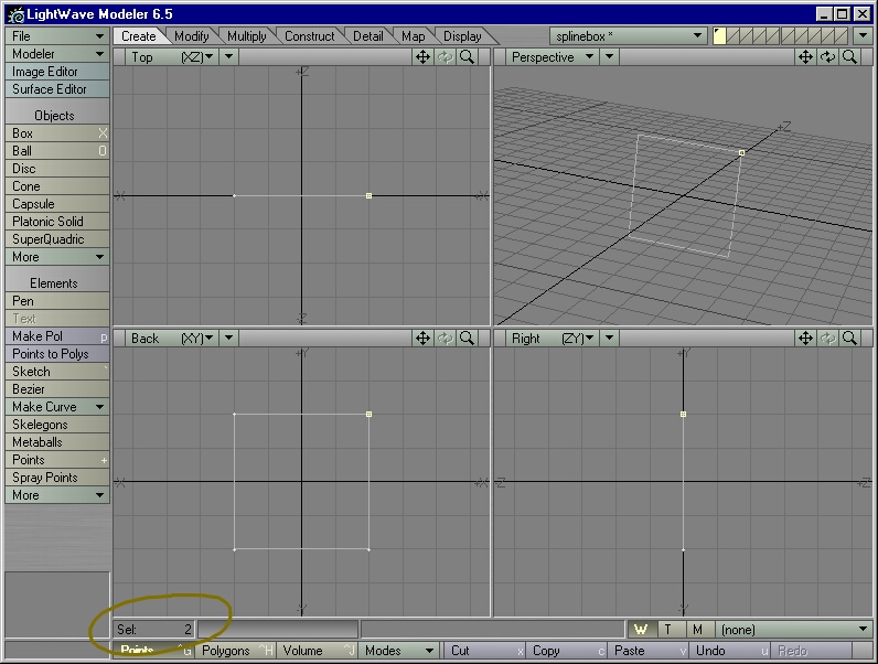
Figure 16
STEP 5: Each pair of points shares the same XYZ coordinates, so each pair looks like a single point. Type m on the keyboard to summon the Merge Points (Construct > Reduce > Merge Points) command. Choose "Automatic," which merges those pairs of points that share the exact same XYZ coordinates. Click on "OK." You should see a dialog box that tells you "2 points eliminated." Click on "OK."
STEP 6: Go back into Polygon Selection mode. If you had unselected the splines, reselect them in a counterclockwise manner. Type Ctrl-f and try patching them again. This time the Patch operation should be successful.
STEP 8: If you already have splinebox.lwo loaded, and if you have any of its points selected in Point Selection mode, deselect them now.
STEP 9: In Polygon Selection mode, select the topmost spline.
We are going to split this spline into two splines. First, though, we must tell Modeler where to split the spline.
STEP 10: Activate the Add Points tool. Left-click on the middle of the topmost spline to add a new point to it.
STEP 11: With the topmost spline still selected in the Polygon Selection mode, enter the Point Selection mode and select the point you just added. Type Ctrl-l (that's a lowercase "L") to Split the spline into two splines (Construct > Subdivide > Split). They share the same selected point, forming a fifth "corner." Nothing will appear to have changed in Point Selection mode.
STEP 12: Return to Polygon Selection mode. The formerly whole topmost spline is now displayed as two splines (Figure 17).

Figure 17
STEP 13: Select all five splines in a counterclockwise fashion, type Ctrl-f, and try to Patch it. No matter what you do, it will tell you "Curves do not cross correctly" (even though they form a boundary and share points at all five corners).
STEP 14: Deselect all but the topmost two splines. Type Shift-z to Merge the two splines into a single spline (Construct > Reduce > Merge Polygons). Select the remaining splines in a counterclockwise fashion and try to Patch it again. This time Patch should work.
STEP 16: In Polygon Selection mode, select the rightmost spline. Type c on the keyboard to Copy it to the clipboard, then type v on the keyboard to Paste it. Deselect everything.
STEP 17: Type m on the keyboard to bring up Merge Points. Choose "Automatic" and click on OK. It will tell you "2 points eliminated."
STEP 18: Select the splines in a counterclockwise fashion and try to Patch them. You will get the "Curves do not cross correctly" error message. The Selection Info tells you that you have five splines selected - the most likely culprit for the failed Patch operation.
STEP 19: Deselect everything, then select the rightmost spline. The Selection Info tells you that you have two splines selected, even though it looks like one spline (Figure 18). You have two copies of the rightmost spline sharing the same exact points.
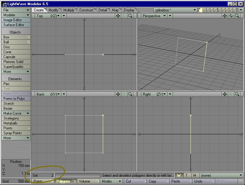
Figure 18
STEP 20: To get rid of the extra copy, type Shift-i to Unify the two splines with shared points into one spline (Construct > Reduce > Unify Polygons).
STEP 21: Select the remaining splines in a counterclockwise fashion and try the Patch operation again. This time Patch should work.
| Tip: You'll encounter this problem whenever you accidentally Paste geometry two or more times in a row and then Merge the points together. If you find that you can't Undo your way out of it, select the offending polygon(s)/spline(s), type m to make sure their points are Merged, and then type Shift-i to get rid of all the unwanted copies. |
STEP 23: In Polygon Selection mode, type c to Copy everything, then v to Paste everything. Then type m to Merge all points.
STEP 24: Starting with the topmost spline, select the splines in a counterclockwise fashion and try to Patch them. This time the Patch operation will be successful, but you'll get a strange-looking patch (Figure 19). Note that the Selection Info tells you that you have eight splines selected.
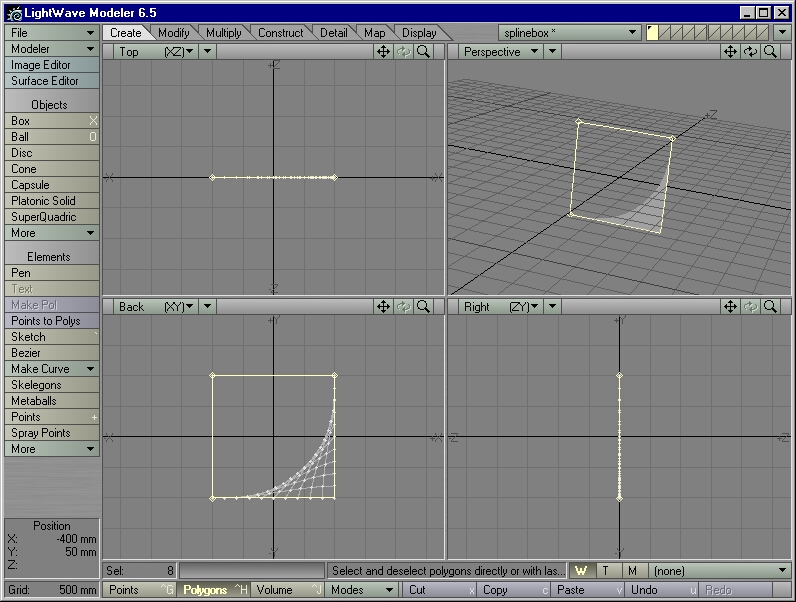
Figure 19
| Note: The Patch operation may be faithfully trying to patch the boundary defined by the last four splines selected - in this case, the two pairs of splines that form the last two "sides" that you selected. |
STEP 25: Undo the Patch operation. Type Shift-i to get rid of the four extra splines. If you Patch the splines again, this time you will get a better patch.
STEP 26: Load splinebox.lwo into Modeler.
STEP 27: Select the topmost spline and type x to cut it out, leaving three sides behind.
STEP 28: Go into Points Selection mode. Select the two topmost points.
STEP 29: Type Ctrl-w to Weld (Detail > Points > Weld) these two points together into a single point. You now have a triangular spline boundary. (Note that the single point took the XYZ coordinates of the last point you selected).
STEP 30: Starting with the leftmost spline, select the other two splines in a counterclockwise fashion and Patch them with a Perpendicular setting of 3 and a Parallel setting of 3. Note how the "triangle" polygons are squeezed into the corner opposite of the last spline you selected (Figure 20). Now, Undo the Patch operation.
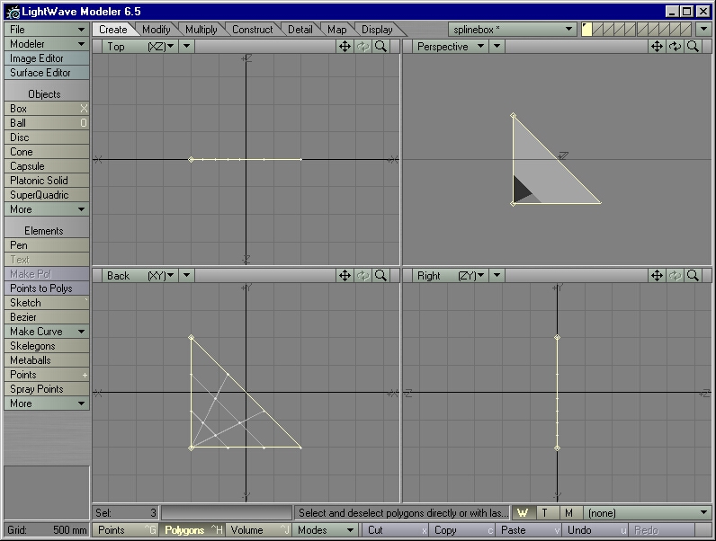
Figure 20
STEP 31: Starting with the bottom spline, select the other two splines in a counterclockwise fashion and Patch them with the same settings as last time (3 by 3). It should look like Figure 21. The "triangles" are now in a different corner - but they are still in the corner that is opposite of the last spline that you selected. Undo the Patch operation again.
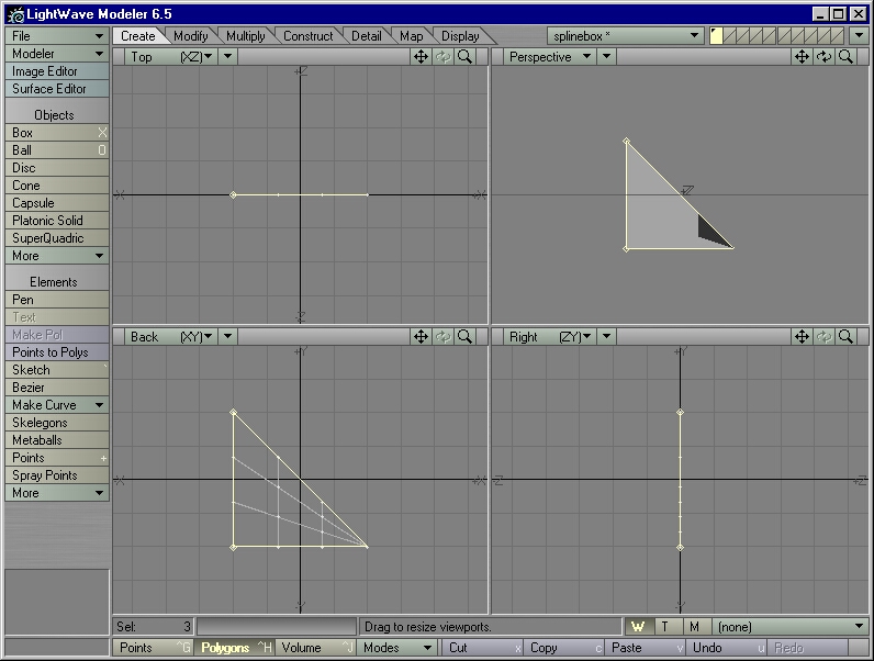
Figure 21
STEP 32: Starting with the rightmost spline (the hypotenuese of this triangle), select the other two splines in a counterclockwise fashion and Patch them with the same settings as before (3 by 3). It should look like Figure 22. Again, the "triangles" are in the corner opposite of the last spline that you selected. Don't Undo the Patch operation this time - we need to take a closer look at those "triangles."

Figure 22
STEP 33: Type " (the double-quotes key) to Invert (Display > Selection > Sel Invert) your selection. Now the patch is selected, and the splines are not selected. Type x on the keyboard to Cut this patch into memory. Go to a new layer and type v to Paste the patch into the new layer.
STEP 34: In Polygon Selection mode, type w on the keyboard to bring up Polygon Statistics (Modeler > Windows > Statistics Open/Close) (Figure 23) All of the polygons in this patch are four-point polygons. The next step will reveal why.
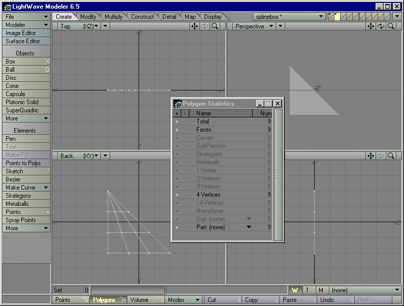
Figure 23
STEP 35: Exit the Polygon Statistics window. Go into Point Selection mode. Select the topmost "point." Note that the Selection Info box says you have four points selected, even though it looks like a single point. Those "triangles" are four-point polygons, then - they just happen to have all of their topmost points lying on top of one another.
STEP 36: Type m on the keyboard, and choose "Automatic" to Merge all points that share the same coordinates. If you look at Polygon Statistics now, you'll see that the "triangles" generated by the Patch operation are now true triangles.
| Tip: If the "triangles" generated by a Patch operation look odd in OpenGL, don't worry. Their "oddness" will disappear when you merge their overlapping points, turning them into true triangles. |
| Technical Note: The Patch operation cannot generate anything but four-point polygons. The Patch operation treats the corner-point opposite of the last spline selected as a "one-point spline." The programmer might have done this to appease the Patch operation's single-minded mathmatical functions ("But I don't wanna figure out a three-sided patch!" "There, there, pretend that this corner point is the fourth 'side.' Happy..?") |
"I can't get the patches to line up. I hate having to Weld all those points just so that I can get a seamless mesh."
They underestimate how literal-minded the computer can be. We can get the patches to line up, without having to "stitch" them together afterwards.
STEP 37: Load the now-infamous splinebox.lwo into Modeler.
STEP 38: Select the top and bottom splines. Add a point to the middle of each spline.
STEP 39: In Point Selection mode, select these middle points and type Ctrl-p to make a new spline. It should look like Figure 24. You now have two adjacent boundaries, ready for patching.
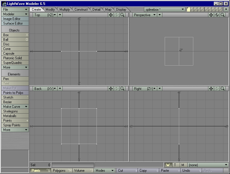
Figure 24
STEP 40: Go to Polygon Selection mode. Starting with the topmost spline, select the splines of the left boundary in a counterclockwise fashion. Patch this boundary with settings of 4 by 4 (Figure 25). Deselect everything.
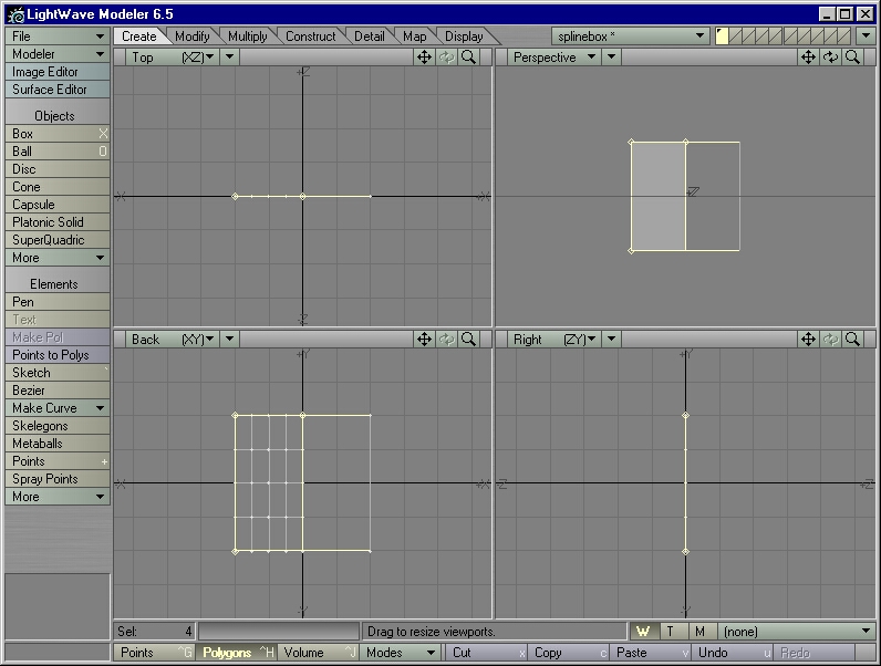
Figure 25
STEP 41: Starting with the topmost spline, select the splines of the right boundary in a counterclockwise fashion. It's OK if you select any faces by mistake - all the Patch operation can see are splines. Patch this boundary with a Perpendicular setting of 4 and a Parallel setting of 2 (Figure 26). Deselect everything.

Figure 26
STEP 42: Type w on the keyboard to bring up the Polygon Statistics panel. Click on the plus sign next to "Faces." All non-spline, non-SubPatch polygons will be selected. Exit the Polygon Statistics panel. Cut and paste the selected faces into a new layer.
STEP 43: Select the points that form the border where the patches join. Selection Info should list 10 points. Type m and set the Merge Points operation to "Automatic." Five points should be eliminated, leaving you with a seamless mesh.
| Note: If you use the same settings and the same spline, the Patch operation will always return the same results (the same point placement along the spline). In the case above, the "same spline" was the spline running down the middle, bordering both patches. The "same settings" made sure that four "rows" of polygons formed each patch, (notice that the number of "columns" in each patch didn't matter, since they had nothing to do with that spline in the middle). |
STEP 44: Return to the layer that has the splines. Select the splines of the left boundary in a counterclockwise order and Patch it with a 4 by 4 setting. Deselect the splines, select the splines of the right boundary in a counterclockwise order and Patch it with a 3 by 3 setting. Take a good look at it (Figure 27).
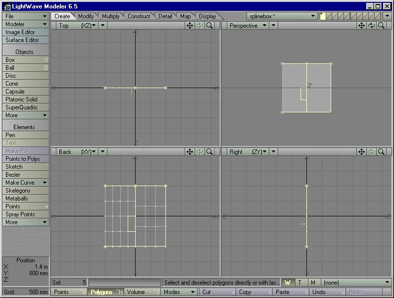
Figure 27
A simple Merge won't make a seamless mesh out of these two patches - the points along the "seam" do not line up. Type u twice to get back to the pre-patched stage.
STEP 45: To the middle spline, add a point somewhere between the topmost spline and the X axis - anywhere but the exact center of the spline.
| Note: When the points of a spline are spaced evenly along the length of the spline, Knots will return results similar to that of Lengths. |
STEP 46: Select the splines of the left boundary in a counterclockwise order (if they are not selected already). Patch them with a 3 by 3 setting with Knots activated in both settings. Deselect the splines. Select the splines of the right boundary in a counterclockwise order, and patch them with a 3 by 3 setting with Length activated in both settings. Look at the result (Figure 28).

Figure 28
Undo the Patch operation and repatch with a 3 by 3 setting with Knots activated in both settings. Now it matches.
STEP 47: Hit u twice to undo both Patch operations. Patch the left boundary with a 3 by 3 setting with Length activated in both settings. Patch the right boundary with a 3 by 3 setting with Length activated in both settings. Because you used the same settings on both patches, they should line up.
STEP 48: For fun, hit u twice to undo both Patch operations. Go into Point Selection mode and select the two topmost points of the middle spline. Type t to activate the Move tool. In the Right view, drag the points towards the negative Z axis. In the Back view, patch both spline boundaries with settings of 10 by 10. It should look like Figure 29. A simple change in the spline cage resulted in a huge change in the patches.
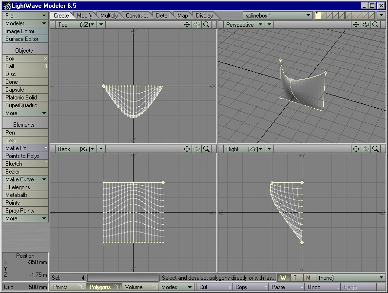
Figure 29
Patching itself is pretty easy, once you know how to do it. The skill of describing a complex object with the fewest possible splines, however, takes some practice.